Common turbo problems & failures Dps sequential turbo kit sequential twin turbo setup 1988-2018 Diagram turbocharger oil flow air turbo diesel through turbochargers fig
Diesel Turbo Diagram | My Wiring DIagram
Diesel turbo diagram What is turbocharger surging? causes of turbocharger surging [complete Diagram of the turbocharged diesel engine
Toyota supra mkiv : types of twin turbo setups
Turbo turbocharger system works work does schematic piping gifTurbo problems turbocharger diagram failures common compressor engine center supercharger turbochargers leaks side difference learning install Diagram of the turbocharged diesel engineHow it works: diesel engine air system.
K04 (lnfTurbocharger ihi ea888 tfsi wastegate schematic turbochargers geometry System engine ford sensor fuel turbo 1993 1994 3l non diesel diagram f350 pump where liter duty super start tempK04 boost redline plumbing lnf saturn solenoid cobalt le5 ss 4l.

Cooling system service by mr. nobody tires gastonia nc
Scheme of the diesel engine turbocharger.Parallel vs. sequential vs. compound Schematic representation of a diesel engine with a turbocharger powerSequential twin turbo diagram november 2013 basic training.
Turbocharger operation fuelDiagram of turbo-diesel system [3]. Turbo diesel engine diagramHow a turbocharger works.

Turbocharger working components types principles engine automotriz used
Auto faction on hubpagesCooling system coolant car gif Fixed geometry turbochargersTurbocharger sketch.
Feilsøking – turbo1 asTurbo works turbocharger turbochargers sequential pakwheels rajon engineer Compound turbo diagramTurbocharger: components, working principles, and types.

Turbocharged diesel
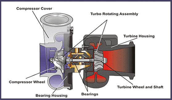
Turbocharger diagram turbine pressure kkk turbo parts housing components part exhaust diesel wheel ultimate compressor oil center inlet 2008 supportTurbo turbocharger works engine diesel cummins system parts ford diagrams detroit gif holset perkins volvo couple 2011 turbocharger inlet hose. 6.6 liter diesel, turbo & exhaust[diagram] twin turbo setup diagram.
Turbocharged diesel engine.Turbo compound twin sequential setup diagram wastegate supra plumbing kevin mkiv twincharged toyota parallel works pipe setups compressors homemadeturbo types The ultimate turbocharger diagramWhat is a turbocharger and how does it work?.

Vgt engine stuck mechanism turbocharged lacks
Diagram of the turbocharged diesel engineHow does a turbocharger work? Turbocharger surging engineeringlearnDiagram of the turbocharged diesel engine.
All about turbochargers – seidel diesel groupSchematic diagram of a turbocharged diesel engine with egr. 93 7.3 non turbo is terrible to try and start even in warm weatherInlet turbocharger silverado pipe gmc sierra exhaust wastegate actuator inl adap liter tubmangmpartsdepot.

Turbocharged diesel engine lacks power due to stuck vgt mechanism
.
.


The Ultimate Turbocharger Diagram - Buy Auto Parts
Common Turbo Problems & Failures

DPS SEQUENTIAL TURBO KIT SEQUENTIAL TWIN TURBO SETUP 1988-2018

Schematic representation of a diesel engine with a turbocharger power

What is Turbocharger Surging? Causes of Turbocharger Surging [Complete

Sequential Twin Turbo Diagram November 2013 Basic Training
